Injection moulding process - structure, workflow, and benefits of modern plastic manufacturing
How is a precise plastic part created by injection moulding, and when does the process pay off? Here you will find the key information on process, materials, tooling, design rules, and economics. From pilot runs to larger series, assemblean delivers injection-moulded parts quickly, reliably, and with ISO-certified quality.
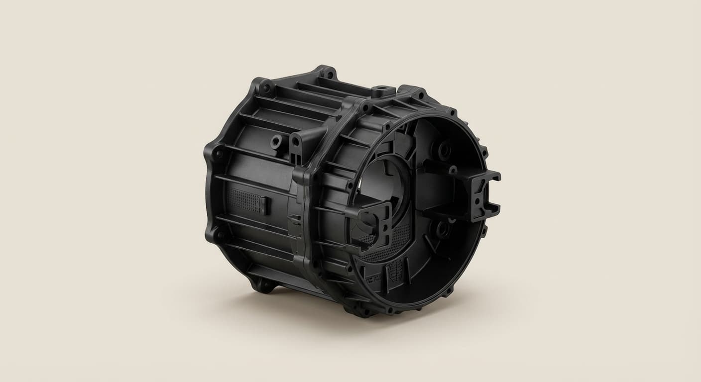
Injection moulding is one of the core manufacturing processes in modern plastics processing. It is used wherever complex components are needed in large quantities and with consistent quality, from automotive and medical technology to electronics and consumer products.
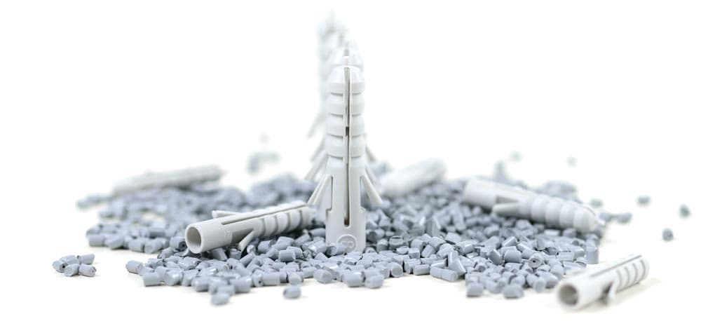
The principle is efficient: plastic granules are melted, injected into a mould under pressure, cooled, and then demoulded. This creates precise parts with defined geometry, high dimensional accuracy, and repeatable quality.
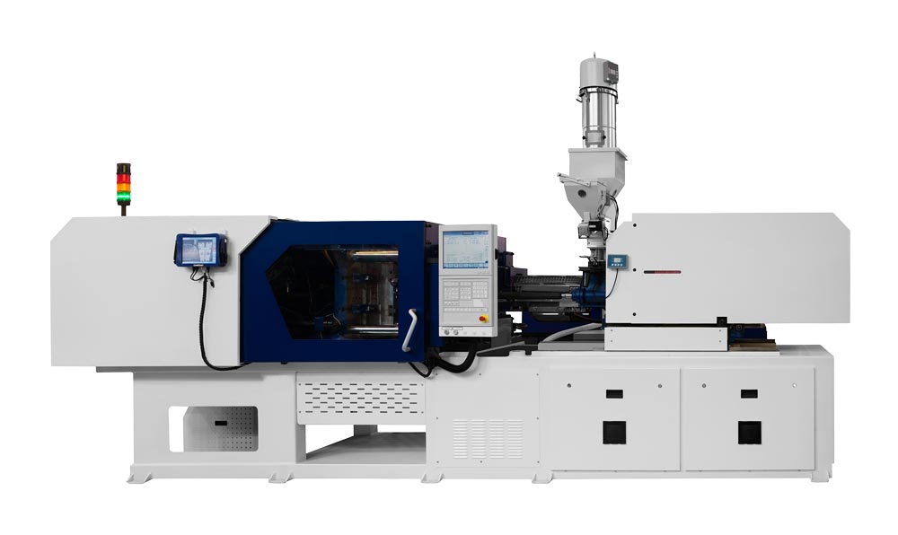
The image shows an injection moulding machine.
Basics of injection moulding
Injection moulding is a primary forming process for plastics. The material is liquefied by heat, shaped inside a mould, and solidifies there.
The technology has developed into one of the most important industrial production methods. Everyday products from toothbrushes to connectors and precision vehicle components are made this way. The target properties determine the material and therefore the injection moulding process.
Injection moulding processes at a glance
Three material families. Three paths to a finished part.
04 / 05 · Cooling & solidification
Thermoplastics
The melt solidifies in the cooled mould.
Thermoplastic injection moulding is the most common variant. Thermoplastics can be reshaped several times by heating, which supports recycling and post-processing.
Melt
Shape
Cool
04 / 05 · Curing
Thermosets
Heat permanently crosslinks the material.
Thermoset injection moulding is used for components that need high dimensional stability and heat resistance, for example electrical parts. Thermosets cure chemically and cannot be melted again afterwards.
Dose
Shape
Cure
05 / 05 · Demoulding
Elastomers
The material crosslinks and stays elastic.
Elastomer injection moulding is used for flexible, rubber-like materials such as seals and vibration dampers.
The illustration shows vulcanisable solid rubber. Liquid silicone rubber (LSR) and thermoplastic elastomers (TPE) need different feeding systems or processes.
Dose
Vulcanise
Demould
Alongside these standard processes, special variants are used depending on the component requirements:
Multi-component injection moulding (2K, 3K) for parts with different materials or colours,
Gas-assisted injection moulding to reduce material use and weight,
Micro injection moulding for very small, precise components, especially in medical technology,
Insert and outsert moulding, where inserts such as metal bushings are overmoulded.
Difference from other processes
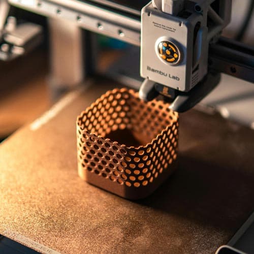
While 3D printing is especially strong in prototyping and small batches, injection moulding is strongest at medium and large quantities because cycle times are short and unit costs are low. Compared with vacuum casting, injection moulding also offers much better repeatability and dimensional stability.
The injection moulding process - step by step
From tool to finished part – illustrated with a thermoplastic.
The injection moulding process consists of coordinated steps. Each step affects the quality and dimensional accuracy of the finished part.
01 / 07 · Toolmaking
The tool defines the shape.
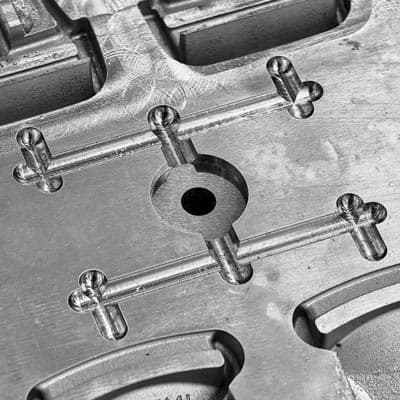
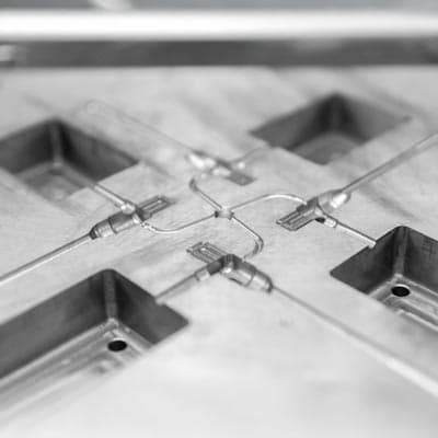
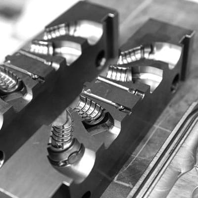
The mould is the core of every injection moulding project. It consists of two mould halves, the cavity and the core. The runner system guides the molten material into the mould; slides, ejectors, or hot runner systems can be integrated depending on the part.
Melt. Mix. Measure.
In the barrel of the injection moulding machine, plastic granules are heated and melted by a rotating screw. The screw transports, homogenises, and doses the material for the next shot.
The cavity fills.
The molten material is injected into the closed mould under high pressure, typically 500 to 2,000 bar. The goal is complete cavity filling without trapped air or excessive pressure.
Hold the shape under pressure.
After filling, pressure is maintained briefly to compensate for volume lost during cooling. This helps prevent sink marks and secures dimensional accuracy.
Make the shape stay.
The mould is actively temperature-controlled, usually through water channels. Correct temperature control is decisive for cycle time and part quality.
Open. Eject. Repeat.
After solidification, the mould opens and ejectors push the part out. The cycle then starts again.
Check the process and the part.
Modern injection moulding machines are digitally connected. Sensors record temperature, pressure, and cycle times in real time.
Monitoring accompanies the whole cycle. Optical inspection is one example; further checks depend on the part.
Start your injection moulding project with us.
Materials and polymers for injection moulding
The choice of plastic determines function, lifetime, appearance, and cost. Injection moulding materials are usually divided into thermoplastics, thermosets, and elastomers.
All three can be processed by injection moulding, but they behave differently and serve different applications. Thermoplastic injection moulding is the most economically important route.
Thermoplastics - the standard in injection moulding
Thermoplastics are by far the most common materials in injection moulding. They are fed as granules, melted, injected into the tool, and solidify again during cooling. This process is reversible, so thermoplastics can generally be remelted, which supports recycling and the use of regranulate.
Typical properties of thermoplastics:
wide range from soft and flexible to stiff and high-strength
good processability and short cycle times
depending on type: transparent, coloured, chemical-resistant, or high-temperature resistant
Examples and applications:
ABS: good impact strength and easy processing, ideal for housings, consumer goods, and interior parts.
PP: chemical-resistant, cost-effective, and flexible, often used in packaging, automotive, and medical technology.
PA: high strength and heat resistance, ideal for technical parts.
PC: transparent, impact-resistant, and temperature-stable, used for optical parts and housings.
POM: excellent dimensional stability and sliding properties, preferred for gears, bearings, and precision elements.
PEEK: high-performance polymer with exceptional temperature and chemical resistance, for example in aerospace and medical technology.
Thermosets - maximum dimensional stability and heat resistance
Thermosets behave differently in injection moulding because they crosslink in a chemical curing process. After curing, they can no longer be melted, only mechanically processed.
In practice, thermosets are used when thermoplastics reach thermal or dimensional limits, for example permanently hot or mechanically loaded electrical housings and components in engine compartments or other high-temperature areas. The trade-off is longer cycle time and stricter tool-temperature and process control.
In injection moulding this means:
the uncured compound is injected into the tool at relatively low temperature
the tool itself is much hotter; the reaction and curing happen there
the reaction produces dimensionally stable, heat-resistant parts, often with larger wall thicknesses
Typical properties of thermosets:
very high dimensional stability and stiffness
good temperature resistance, often well above 150 °C
very good electrical insulation
not meltable and only partly recyclable, often as ground material
Elastomers - sealing, damping, flexibility
Elastomers are rubber-like plastics that stretch under load and return to their original shape. In injection moulding they are processed similarly to thermosets: crosslinking takes place through heat in the hot tool, often by vulcanisation.
They are useful when parts must stay flexible, absorb movement, or isolate vibration, for example in drive technology, mechanical engineering, and sealing systems.
Special features in injection moulding:
the material is drawn into a dedicated screw as powder or strip material
the barrel is only moderately heated to avoid premature crosslinking
the tool is much hotter and performs the actual vulcanisation
vulcanisation time can be much longer than preparation time, so multiple clamping units or tools are often used
Typical properties of elastomers:
soft to medium-hard, rubber-like behaviour
high recovery even under dynamic load
good damping of vibration and impact
often good resistance to media and weathering
Additives and fillers - fine-tuning the material
Many injection moulding materials are upgraded with additives and fillers so mechanical, thermal, electrical, and optical properties can be adjusted precisely.
Glass- or carbon-fibre-reinforced grades behave differently during filling, shrinkage, and surface formation than unfilled materials. Material choice should therefore always be considered together with part geometry and tool concept.
Typical additives:
reinforcing fibres such as glass or carbon fibres for higher strength, stiffness, and temperature resistance
mineral fillers such as talc or chalk to reduce warpage and influence shrinkage
UV stabilisers, flame retardants, and antistatics for outdoor use, fire protection, or ESD protection
colourants and masterbatches for defined colours, effects, and surface impressions
At assemblean, we support material selection already during the design phase based on temperature requirements, mechanical load, and desired surface quality. If the material you need is not listed, contact us; we can coordinate production with your desired material.
Post-processing - surface quality for injection-moulded parts
SPI standard
Application
Method
Surface roughness (Ra um)
A-1
High-gloss polished parts
Grade #3, 6000 grit diamond
0.012 - 0.025
A-2
High-gloss polished parts
Grade #6, 3000 grit diamond
0.025 - 0.05
A-3
Highly polished parts
Grade #15, 1200 grit diamond
Tool types in injection moulding
The injection mould is the central element of every project. It determines cycle time, surface quality, dimensional accuracy, and ultimately economics. Different tool concepts are used depending on quantity, part geometry, and material.
The main tool types are:
Single-cavity tools
Tools with one cavity produce exactly one part per cycle. They are useful for prototypes, smaller series, complex geometries, or dimension-critical parts. Design effort is lower and changes to parting lines, gates, or venting can be implemented comparatively quickly.
Unit costs are higher because only one component is produced per shot.
Multi-cavity tools
Multi-cavity tools contain several identical cavities and produce several parts per cycle. This significantly increases output and reduces part cost at medium to high quantities. Runner and cooling design is more complex because all cavities must fill and cool evenly to avoid dimensional deviations and weld lines.
Family tools
Family tools combine several different but related components in one mould, for example the upper and lower halves of a housing. All parts are moulded in one cycle, saving tool cost because each component does not need a separate tool.
The parts should have similar volumes and wall thicknesses so filling and shrinkage remain balanced.
Gate systems in injection moulding
Single-cavity, multi-cavity, and family tools describe how many and which parts a mould produces per cycle. Independently of that, each tool can use a cold runner or hot runner system, meaning the way the plastic melt reaches the cavities.
Cold runner tools
In a cold runner tool, the plastic in the runner solidifies together with the component. The runner is separated afterwards and, depending on the material, recycled or discarded.
Cold runner systems are robust, relatively simple, and suitable for nearly all plastics. They fit small to medium quantities, but create extra material use and more visible gate marks.
Hot runner tools
Hot runner tools keep material in the distribution channel molten through heaters, so only the part solidifies when the mould opens. This reduces material waste, often shortens cycle time, and allows precise control of pressure and temperature.
It is especially useful for expensive or technical plastics and high-volume production, but investment, maintenance, and design complexity are higher.
Design guidelines for injection-moulded parts
Good part design is the basis for a stable and economical injection moulding project. The most important decisions are made during design because they affect quality, cycle time, and cost.
Wall thickness
Uniform wall thickness helps avoid sink marks and warpage. Depending on material, a typical range is 1-4 mm.
Draft angles
At least 1° to 2° per side makes demoulding easier.
Ribs and reinforcements
Ribs increase stiffness without increasing the main wall thickness.
Radii
Internal radii should be 0.5-1 x wall thickness to avoid stress peaks.
Undercuts
If undercuts cannot be avoided, they must be feasible with slides, lifters, or ejector concepts.
Gate types
Pin, film, tunnel, or hot runner gates are selected according to part geometry.
Already during design, assemblean supports customers in applying these guidelines. If needed, a manufacturability review identifies and optimises risks such as undercuts or uneven wall thickness.
Typical defects in injection moulding
Even with careful design and precise tooling, typical defects can occur. The important point is to know their causes and prevent them in the process.
Flow lines
Flow lines occur when the melt front cools unevenly or overlaps in areas with different flow speeds. They appear as visible lines or matte zones. Uniform wall thickness, higher injection speed, optimised tool temperature, and adjusted gate position help distribute material more evenly.
Weld lines
Weld lines form where two flow fronts meet and do not fully bond. They are often caused by low temperature or low injection speed. Higher tool and melt temperature, adjusted pressure, and better gate design help the fronts merge more reliably.
Air traps and bubbles
Air traps and bubbles are usually caused by insufficient venting or excessive injection speed. Precise vent grooves, adjusted filling speed, careful drying of hygroscopic plastics, and a stable holding-pressure phase help prevent voids.
Short shots
Short shots are incompletely filled parts. They occur when material pressure or temperature is not sufficient to fill the mould. Higher injection pressure, improved venting, optimised runners, or multi-point injection can stabilise flow.
Sink marks
Sink marks appear over ribs or thicker wall sections when the material shrinks unevenly during cooling. Uniform wall thickness, optimised holding pressure, and homogeneous tool temperature reduce the risk.
Flash
Flash is caused by excessive injection pressure, worn parting surfaces, or insufficient clamping force. Regular tool maintenance and correct machine sizing prevent material from escaping at the parting line.
Warpage
Warpage results from uneven cooling or internal stresses. Symmetrical wall thickness, even temperature control, and sufficient cooling time reduce deformation after demoulding.
Start your injection moulding project with us.
Advantages and disadvantages of injection moulding
Injection moulding combines high precision with economical series production. Few processes can produce complex plastic parts so efficiently, repeatably, and with attractive surfaces. Still, both strengths and limits matter when choosing the right manufacturing strategy.
Advantages of injection moulding
1. Economical series production
After the tool has been built, injection moulding offers very low unit costs. The process is highly automated, delivers consistent quality, and is ideal for medium to large quantities.
2. Precision and repeatability
Every part follows the mould geometry. Tolerances in the range of a few tenths of a millimetre are common, making the process suitable for components that must fit precisely or be processed automatically.
3. Broad material range
From ABS and PP to engineering plastics such as PA and POM and high-performance materials such as PEEK or PEI, injection moulding covers many requirement profiles. Additives and fillers allow targeted changes in strength, surface hardness, or chemical resistance.
4. Design freedom and functional integration
Complex geometries, snap fits, ribs, and living hinges can be formed directly in the tool. Several functions can be combined in one part, reducing assembly steps.
5. High surface quality
Precise tool machining creates surfaces from high gloss to fine texture, often without post-processing.
6. Short cycle times and scalability
A complete production cycle often takes only seconds. Multi-cavity tools produce several parts at once, lowering unit cost and enabling high output.
Disadvantages and limits of injection moulding
1. High initial tooling cost
The largest upfront cost is toolmaking. Depending on complexity, the investment can reach several thousand euros, so the process usually pays off from medium quantities upward.
2. Longer lead time
Tool design and manufacturing take time. Design changes after tooling usually require tool modifications or a new tool.
3. Design requirements
Injection moulding needs manufacturing-friendly design: uniform wall thickness, draft angles, and as few undercuts as possible.
4. Tool maintenance and wear
Glass-fibre-reinforced plastics in particular increase tool wear. Regular cleaning and maintenance secure part quality over the tool lifetime.
5. Limited economics for small batches
Below roughly 500 to 1,000 parts, additive manufacturing or vacuum casting is often more economical. assemblean helps choose the right path from 3D printing and rapid tooling to full injection moulding series.
Comparison
When does injection moulding pay off, and what are the alternatives?
Injection moulding pays off especially when medium to large quantities are needed.
The most important cost drivers are:
Tooling cost: one-time investment depending on complexity and number of cavities.
Material cost: plastic granules, additives, and colourants.
Machine time: cycle duration and post-processing.
Setup and maintenance time.
The economic advantage is scalability: the larger the quantity, the lower the price per part. From a few hundred parts onward, injection moulding can become cheaper than additive manufacturing or milling.
Break-even example:
If a tool costs EUR 8,000 and 10,000 parts are produced, tooling cost per part is only EUR 0.80. Once material and machine costs are added, injection moulding is usually clearly ahead at this volume.
The key decision is the relationship between fixed costs, such as tooling and setup, and variable unit costs. Higher production volume amortises fixed costs. Alternative processes such as 3D printing or CNC machining remain better for small quantities or frequent design changes.
Practical orientation for the manufacturing strategy
Prototype phase / small batch (about 1-500 parts)
In early phases, short iteration cycles and low start-up cost matter more than minimum unit cost. Additive manufacturing is often the first choice. SLS and MJF deliver robust functional prototypes and small series without tooling, while SLA offers very fine surfaces and accuracy.
Vacuum casting is another proven small-series route using silicone moulds made from a master pattern.
Pilot series / validation (a few hundred to a few thousand parts)
Rapid tooling becomes relevant here, for example 3D-printed or softer metal mould inserts. It allows real injection moulding materials and more realistic cycle parameters at lower tool cost and limited tool life. Vacuum casting can also bridge the gap when surface appearance and material choice fit.
Series production (several thousand to hundreds of thousands of parts)
This is where injection moulding is strongest. Hot-runner multi-cavity tools reduce unit cost through short cycles and high output while dimensional accuracy remains stable. A sensible path can be rapid tooling, then pilot series, then multi-cavity tooling.
Special cases and additions:
For thin-walled covers, blisters, or housing shells, thermoforming with 3D-printed moulds can be cost-effective in low quantities. For soft or medical parts, silicone parts can be cast economically with 3D-printed mould inserts.
These bridge methods close the gap between prototype and series without immediately investing in durable steel tools.
Industries and application examples
Injection moulding is one of the most versatile industrial manufacturing processes. Nearly every industry benefits from its design freedom and repeatability:
Automotive: housings, brackets, clips, connectors, and controls.
Medical technology: precision parts, disposable components, and laboratory containers.
Electronics: plugs, insulators, sensor housings, and control-unit components.
Consumer goods: packaging, household products, and toys.
Machinery and equipment: functional housings, handles, and covers.
Example: injection moulding in the automotive industry
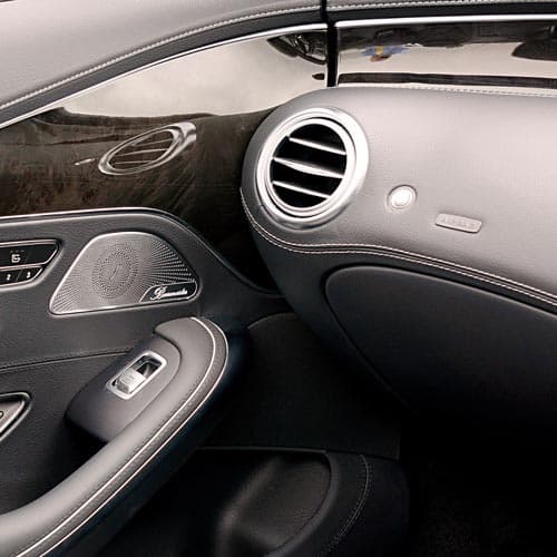
In the automotive industry, injection moulding is used for technical plastic components in interiors, such as ventilation elements, trim parts, and brackets. These components must look good and withstand high temperature and load requirements.
Glass-fibre-reinforced plastics make it possible to produce lightweight, dimensionally stable, vibration-resistant parts. Injection moulding also allows several functions to be integrated into one component, for example clips, sealing lips, or guide features.
The high repeatability ensures that components from different production batches fit together reliably in modern vehicle assembly.
Do you want to start an injection moulding project?
Injection moulding is the key technology for economical, precise, and repeatable plastic parts. Its modular process, from material selection and tool technology to quality assurance, offers flexibility for many applications.
assemblean combines this proven technology with a modern, digitally managed production structure. Customers benefit from:
ISO-certified manufacturing,
one central contact for all project phases,
transparent process data, and
flexible lead times from prototypes to high-volume production.
This makes injection moulding efficient, plannable, traceable, and future-ready.