Mould design
The first important die casting design note concerns the mould design. The mould must be able to withstand high pressure in the manufacturing process and allow smooth part production.
To do this, you should keep in mind during the design that the part can be easily removed from the mould without damage. Therefore, consider features such as parting lines at the beginning of your part design.
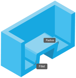
Fillets and radii
Fillets and radii are other important design features in die casting. They allow you to create smooth transitions between surfaces and avoid stress build-up. This affects the strength, durability and appearance of your parts.
Die casting design tips for fillets and radii:
- The size and shape of fillets and radii are application specific, but should not be smaller than 1mm.
- Larger radii are recommended for areas with higher loads.
- To prevent stress accumulation, avoid sharp corners and edges.
- Be aware of the radius when two surfaces meet, as these can affect the strength of the joint.
- Use fillets and radii throughout the design to maintain the strength and smoothness of the component.
Add draft angles aligned with the mould opening direction. This will ensure that your part can be removed from the mould without damage to the surface. Usually they range from 1 to 3 degrees, but can be greater for more complex parts.
Wall thickness
When designing the wall thickness, consider the desired stiffness, strength and weight of your product. The wall thickness affects the cooling time of the mould and the pressure that can be applied to the mould.
The wall thickness is application specific and depends for example on the mould size, the material used and the production processes.
Some minimum wall thicknesses for castings are:
- Magnesium: 1.016 - 2.54 mm
- Aluminium: 1.016 - 2.032 mm
- Zinc: 0.381 - 0.889 mm
Ribs and outside corners
You can use ribs to reinforce component walls and increase stiffness. They also allow you to distribute loads more evenly and thus prevent deformation. With outside corners you can create sharp transitions between surfaces.
The thickness of ribs and outside corners is also application-specific. For example, thicker ribs are important for components that are under heavy loads.
Add ribs to the thinnest wall first so that this component does not become too thin. In addition, the spacing between ribs should be evenly distributed.
Another design tip: Avoid outside corners to prevent stress accumulation. If outside corners are necessary, their radius should be as large as possible to reduce stress.

Windows and holes
Windows and holes allow fluids to flow through or create a connection between two parts. You should consider them when designing your part so that they do not affect the strength and stability of the final product.
In most cases, windows are rectangular in shape and are located at the top or side of the mould. Holes, on the other hand, can take different shapes and lie anywhere in the mould.
Windows and holes should be rounded or fluted and located away from sharp corners and edges. In addition, windows and holes on the side of the mould may require demoulding bevels with larger angles.
Finished features
Some features are usually only possible after the castings have been cast. This finishing is an additional process step that increases production time and production costs.
If post-machining is necessary, follow these die casting design tips:- Try to add as few reworked features as possible to keep costs comparatively low.
- Design the features to be as simple and accurate as possible.
- Choose the location of the features so that as little material as possible has to be removed.
- The tolerances of the features should be realistic and achievable.
- You can also add reworked features by inserting cores in the design phase. Cores create internal components in the casting by creating holes and other features in the final casting.
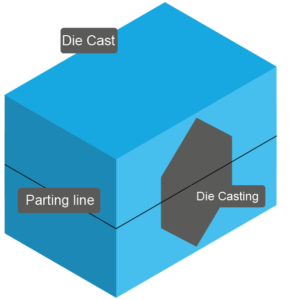
Parting lines
One feature that can be machined during finishing is the parting line. This is the line where the two halves of the mould meet. It is usually at the top or side of the part. The parting line is important in the design of the die cast part as it is where a visible seam will be created on the final product.
Make sure the parting line is where it is least visible. Also note the thickness of the line. This is because lines that are too thin can cause the part to break when it is removed, while parting lines that are too thick can cause uneven surfaces and imperfections in the final product.
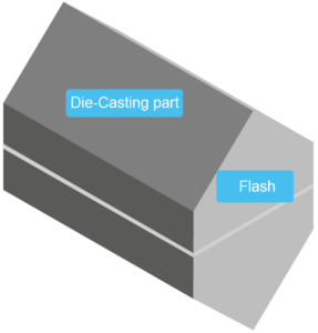
Often there is also extra material that settles on the parting line. This extra material is called flash and can be removed during finishing.
Surface treatment grades
The final step in the casting process is the surface treatment. The type of treatment depends on the area of application of your end product.
It is divided into different grades:
Grade 1 (Utility Grade) - for basic use.
Grade 1 is also called Utility Grade. This surface after casting does not need any cosmetic treatment and this grade is best suited for castings with coatings.
Grade 2 (Functional Grade) - functional & simple
The 2nd grade is the Functional Grade. It is used for grinding and painting and therefore for castings with decorative coatings.
Grade 3 (Commercial Grade) - for commercial use
Grade 3, also called Commercial Grade, is suitable for electrostatically painted and custom surface treatment. It is mainly used for structural components that are used under high loads.
Grade 4 (Consumer Grade) - for end-user use.
As grade 4 is intended for consumer use, the surface does not have any disturbing defects. Therefore, this grade is suitable for decorative end products.
Grade 5 (Superior Grade) - for special quality requirements
The 5th grade has a micrometre-precise application of the coating. It is best suited when the end products are bearings for seals and gasket seats.

