Size restrictions
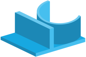
Size restrictions should be observed, as exceeding these dimensions can lead to problems during printing. Each 3D-printing process has its own size restrictions.
With fused deposition modelling (FDM), the maximum dimensions for components are 914 x 610 x 914 mm with a minimum feature size of 0.2 mm.
With the stereolithography (SLA) process, components with maximum dimensions of 480 x 480 x 560 mm can be printed. The minimum feature size is 0.1 mm.
With direct metal laser sintering (DMLS), components with maximum dimensions of 250 x 250 x 325 mm can be printed. The minimum feature size is 1.5mm for structural features and 0.75mm for external features. In addition, the layer thickness is 0.02 to 0.08 mm, depending on the material.
The maximum dimensions for the Multi Jet Fusion (MJF) process are 380 x 284 x 380mm, however the recommended dimensions are 356 x 280 x 356mm.
Very small parts can also be printed, but these also have minimum sizes. The minimum size for hole diameters with a thickness of 1 mm is 0.5 mm. For a height of 10 mm, the minimum pin diameter is 0.5 mm. For embossing and engraving, the font size should be 6 pt. The minimum spacing for a thickness of 1 mm and between walls is 0.5 mm.
Support structures
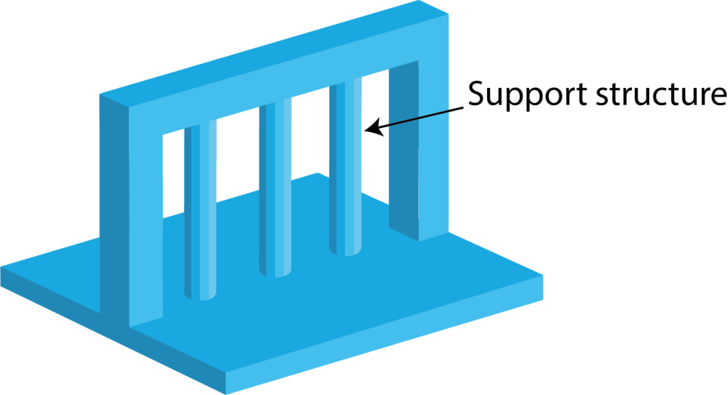
In FDM, components are manufactured layer by layer. If an upper layer is not adequately supported by subsequent layers, it can collapse. This can occur with overhangs and bridges, i.e. horizontal connections between two anchor points. As a solution, you can reduce the distance between the anchor points. Or you can add support structures that you remove during post-processing.
The DMLS process is similar. Support structures are also necessary to reduce warping of the 3D print, anchor the part to the print bed and prevent the part from shifting due to the force of the DMLS coater. However, support structures can lead to higher manufacturing costs. More favourable alternatives would be the construction of angles equal to or less than 30° and the use of fillets at corners.
In carbon DLS 3D-printing, the support structure should be made from the same material as the object itself. It should be shaped in such a way that as few post-processing steps as possible are required. As there are few post-processing methods with DLS, supported areas such as elastic polyurethanes can remain visible.
Support structures in polyjet 3D printing are printed from a special, water-soluble material. This makes them easier to remove after printing, as the part only needs to be rinsed with water.
Tolerances
For correctly manufactured parts, you should follow 3D-printing design tips on tolerances. The tolerances depend on various factors, such as the size of the printer, limitations due to the print bed or limitations due to the print material. For FDM 3D-printing, the achievable tolerance is at least 0.3mm.
In the DMLS process, parts are produced with tolerances of 0.1mm to 0.2mm. As tight tolerances are associated with higher manufacturing costs, they should only be specified for necessary features. For example, for components that must fit together with others. Take geometric properties into account, as residual stresses during printing can lead to unevenness and tolerance deviations. If the designed component requires a high degree of flatness, DMLS is not the best choice.
With a dimensional accuracy of ±0.2mm, the HP MJF process can print parts up to 100mm and 0.2% above this value. These values are measured after sandblasting.
With Polyjet 3D-printing, thin layer thicknesses of 0.004mm are applied. Tolerances of ±0.1mm are achieved for the first dozen mm and ±0.05mm for the following mm.
In the Carbon DLS process, separate tolerances apply for different parameters:
- For the layer thickness: 0.001 mm
- For the gap dimension: 0.6 mm
- For the accuracy: +0.3% or -0.3%
- For the wall thickness: 1.0 mm
Holes
The printing of components with holes varies from process to process.
In the FDM process, holes that are too small are usually printed because each additional layer compresses the circumference of the previous layers. The reduction in size is proportional to the ratio of hole diameter to nozzle diameter.
The slicing software normally takes the hole reduction into account beforehand. However, this process is not always accurate. If the accuracy of a hole is important, it can be drilled after printing.
To ensure that the holes are not closed during printing in SLA 3D printing, they should be designed with a minimum diameter of 0.75mm. If holes are longer than 12mm, the minimum diameter can be reduced slightly.
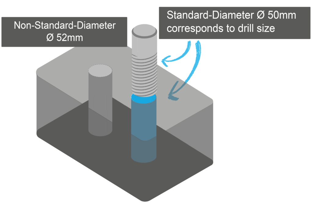
Polyjet 3D printing allows holes to be printed directly. However, it is recommended that you plan standard diameters and drill them after printing. If printed holes are necessary, you should use a minimum diameter of 0.5 mm. This diameter is also suitable for non-functional pens. A minimum diameter of 2mm is suitable for functional pens. As a further option, you can also use prefabricated standard pins.
Assemblies
The high accuracy of HP MJF 3D printing allows fully functional assemblies to be printed. Components require a minimum clearance of 0.4mm or 0.2mm for mating parts when assembled after printing.
Components printed together should have a minimum gap of no less than 0.7mm so that individual parts do not fuse together to form a solid. If the wall thickness of a part is over 50mm, you should increase the minimum distance.
In order to prevent individual parts from merging into one body during the SLA process, minimum distances of 0.5mm between moving parts and 0.2mm for assembly connections should be designed.
In polyjet 3D printing, the individual parts for complex assemblies are usually printed individually first and then assembled. The contact surfaces should have a minimum tolerance of 0.6mm. This takes into account friction effects that are not included in most CAD programmes. To improve the stability of the connections, you should use smooth contact surfaces with recesses and matching protrusions on the opposite side.
Embossing & engraving
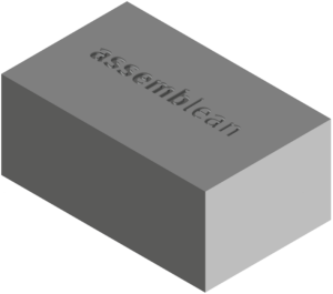
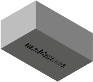
For embossing & engraving your parts, there are important 3D-printing design tips you should know. SLA 3D printing is suitable for very precise embossing and engraving, including text. Engraved features should be at least 0.4mm deep and 0.5mm wide. Embossed features should have a height of 0.3mm and a width of 0.4mm.
For engravings using the polyjet process, both the depth and width of the features should be 0.5mm. A minimum height of 0.5mm and a minimum width of 0.8mm are required for embossing.
You can use the MJF process to print high-resolution numbers, drawings and texts. Do not go below the minimum height and depth of 1 mm. This prevents the image from wearing off during post-processing and guarantees good legibility.
In general, the component should be upside down for embossing and face up for engraving in order to achieve the best resolution.
Distances between features
During DMLS 3D-printing, the laser emits heat to the surrounding powder. This creates a melt that is larger than the diameter of the laser. As a result, closely spaced features can melt together.
It could also create areas of unsintered powder that could get stuck between sintered areas.
To avoid these problems, leave at least 0.5mm space between features.
