The state-of-the-art manufacturing techniques CNC-milling and CNC-turning offer precision, repeatibility and consistency. CNC-milling involves computer-assisted machines to remove material from a workpiece. CNC turning turns a workpiece on a turning machine while a cutting tool shapes it. For optimal manufacturing of your parts, consider some CNC design tips.
Avoid features that are not suitable for CNC manufacturing
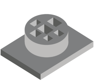
Avoid design features that cannot be CNC machined.
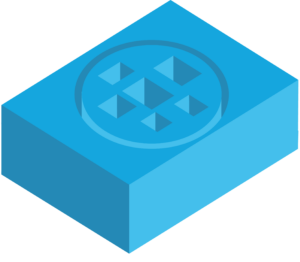
For example, if you need a circular shape with milled square holes, as in the picture, the material around the circle must be cut. This can take a lot of time.
It is easier to cut the part from a block. This prevents unnecessary material removal.
Another example of a similar feature is curved holes. If you need this feature, it is recommended to use electrical discharge machining (EDM) instead.
Avoid unnecessary external features
Some external features are unsuitable for machine production. Therefore, always consider in your design what machining process is required for a feature.
Pay attention to the accuracy of the required features instead of the external features. You can use finishing processes afterwards to improve the exterior.
Avoid high and thin walls
Important CNC design tips concern the part walls. Unavoidable vibrations during machining can cause walls that are too thin to bend or break.
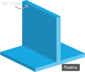
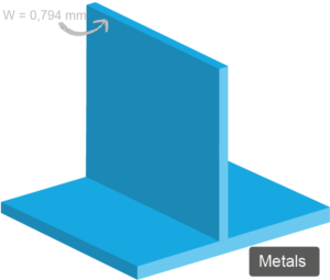
For metals, the standard for minimum wall thickness is 0.794mm and for plastics 1.5mm.
For better rigidity of the material, the wall thickness and height should be adjusted. Generally, the higher the wall, the thicker the wall needs to be. However, the walls should not be too thick either. The rule for wall thickness is a width to height ratio of 3:1.
If a wall is sloped by 1,2 or 3 degrees, so that it tapers instead of being vertical, this can make it easier to work with because less excess material is left behind.
Add a radius, for removing perpendicular inner edges.
Since cutting tools are mostly cylindrical, it is not possible to create sharp inner edges. Therefore, you should add a radius to the inside edges to prevent unnecessary wear on the tool.
The additional radius should be 130% of the radius of the cutting tool. If you need sharp inside edges, you can add undercuts instead of reducing the radius.
Design cavities accurately
To lighten a part or to accommodate other parts in an assembly, some parts have right-angled corners or small pockets on the inside corners. However, 90-degree inside corners and small pockets are usually too small for larger cutting tools. Therefore, the material must be removed from the corners with smaller and smaller tools.
Different tools have to be used for this. Such a tool change always increases the machining time and thus the project costs. Therefore, determine whether you need the inside pockets to save unnecessary costs.
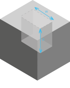
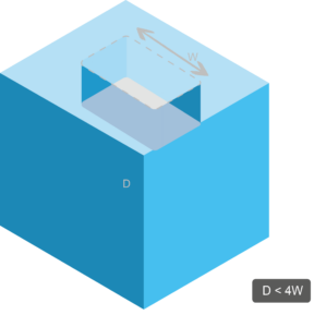
In addition, too deep inside pockets can lead to problems with the tool. Tools could get distracted, get stuck or even break. Therefore, the depth should not exceed 3-4 times the width. If you need greater depths, it is recommended to design the part with a variable cavity depth.


Avoid features that are too small
Extremely small part features make machining difficult and increase costs. Features smaller than 2.5 mm are difficult to process because most CNC machines have a minimum tool diameter of 2.5 mm.
This requires special tools, which then increases manufacturing time and costs.
Design holes with standardised heads
Use standardised drill heads to produce bores quickly and accurately. This means that no broaches or end mills are needed to bring the hole to specific dimensions.
It is important to note that steps of 0.1 mm are used for holes up to 10 mm in diameter and steps of 0.5 mm for larger holes.
Also make sure that the depth of the hole should be four times its diameter. You can also create deeper holes, i.e. up to ten times the hole diameter, but this increases the cost.
Avoid inscriptions that are too small
If you need text on your parts, you can apply it in the finishing process or engrave it by laser.
Note here that smaller fonts can be expensive. This is due to the small indexing cutters that work at a slow speed. This increases the machining time and thus the production costs.
Larger fonts can be milled faster and cheaper. It is also advisable to use recessed rather than raised lettering, as raised lettering requires material to be removed.
Further CNC design tips
If you have any further questions regarding the design of CNC turned and milled parts, please do not hesitate to contact us. We will realise a manufacturable solution with you and support you throughout the entire production process. You can request your quote online or by e-mail.