Injection molding offers the optimal way to scale production. Primarily suitable for high-volume production, you can adapt the process to your production needs by selecting the material of the injection mold. Thus, the process can be worthwhile even for a small series of 100 parts. At first glance, it all seems quite simple. However, there are injection molding design tips that you should keep in mind when designing your parts.
Suitable material
Various materials can be used for injection molding, each with different properties. An important injection molding design tip is to decide which material meets your requirements.
Suitable materials for injection molding include polypropylene (PP), polyethylene (PE), ABS or nylon (PA). Polypropylene is one of the most commonly used injection molding plastics, often used for packaging. It can be welded and has very good chemical resistance.
Polyethylene (PE) also has a high chemical resistance. Along with polypropylene, PE is the most common plastic and is also used for packaging and films, but is also used more frequently for pipes or cable insulation. Polyethylene is light, elastic and has high impact strength.
ABS is also convincing due to its high impact strength. With its low density and good dimensional stability, ABS is a cost-effective plastic. The main areas of application are the manufacturing industry, electronics applications and vehicle construction.
Nylon (PA) is a material used in the automotive sector for sturdy mechanical parts. It has a high melting temperature and is wear resistant. It is also used for applications that require good chemical resistance and high strength.
Wall thicknesses
Other design tips involve wall thicknesses. Generally, the thinner the walls, the less material is needed and the shorter the cycle time, which can save you money. But walls should be designed with the desired strength, stiffness and weight of your end product in mind.
For some applications, thinner walls will suffice. Thinner walls shorten lead times and reduce the cost of your components. In most cases, a wall thickness of 1.5mm-2.5mm is sufficient, but there are also recommendations for minimum wall thickness for each material.
To avoid damage to components, wall thicknesses should be kept as uniform as possible. This is because uneven wall thicknesses and cross-sections can lead to cracks. They can also cause the material to cool unevenly. Consequently, this causes the material to shrink and shrinkage cavities to form.
If different wall thicknesses are unavoidable, the difference in thickness should not exceed 15% of the nominal thickness. A tool for determining the thickness is the Heuvers circle method. Here, the ratio of adjacent circular cross sections in each case should be close to one.
In addition, uniform transitions between thin and thick walls are recommended. Thin sections cool faster than thick ones after they are ejected from the injection mold. Sudden transitions can cause sink marks and deformation.
Radii
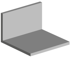
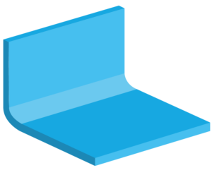
One of the most important injection molding design tips is to consider radii. With radii and rounding, you can prevent further damage and weak spots on your parts.
Radii and rounding make parts easier to eject. This is because rounded corners are less likely to get stuck during ejection than sharp corners.
Sharp corners create stress concentrations that lead to weaknesses and cracks in parts because molten metal is made to flow through corners or into corners. Radii help smooth out stress at corners. If more stress is placed on a part, a larger radius should also be selected.
Also, making parts with sharp corners can be expensive for you. This is because a tool with sharp corners can only be made with special tools. Sharp corners are mostly unavoidable only for parting surfaces.
For the size of the roundings, the wall thickness of the parts should also be taken into account. To avoid material accumulation at transitions between wall thicknesses, the fillets should meet certain dimensions. For transitions between the same wall thicknesses, different dimensions should be met than for transitions between different wall thicknesses.
Ribs
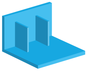
Another injection molding design tip: Use ribs to strengthen your parts! Ribs and wedges reduce material consumption and prevent warpage, sinkage and gaps.
Ribs are essential for structural components. It is advisable to add them instead of increasing wall thickness. This allows you to save material.
When designing parts, you should consider the dimensions of the ribs. To lower the casting stress of your parts, the ribs should be thinner than the wall thickness. The thickness of the ribs depends on the stress at the corresponding location. But it should not be more than 0.8 times the wall thickness.
In addition, with ribs arranged on both sides, an offset is required to prevent material accumulation and thus shrinkage. It is better to use ribs offset than centered on one point.
Cores
When ribs and walls must meet, cores can be useful. Material buildup can occur at these points and lead to shrinkage. Cores can prevent material buildup at these junctions.
However, cores are expensive and can make molding difficult. Therefore, they should be avoided whenever possible and open cross sections should be aimed for.
Complicated castings require multiple parting planes or additional cores. Better design can save division planes and cores.
If cores are necessary, they should be designed as simply as possible. This will keep the cost of core making low and improve the economy of the process.
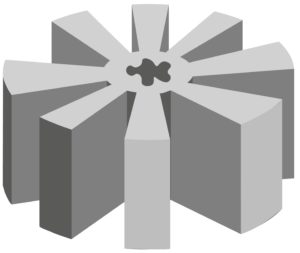
Cores should also be stored carefully because the liquid metal gives them a large large. Make sure that the cores are stored on both sides. This is because if cores are stored on one side, the core supports contribute to the formation of pores and defects.

Drafts
To prevent further damage during part production, there are some injection molding design tips when designing your parts for casting. Damage or problems can occur at various points in the molding process. For example, when lifting out your parts.
Parts can get stuck when lifted out, causing damage. You should therefore provide lift-out bevels on the outer surfaces of the model, otherwise the lift-out process cannot take place without damage. With lift-out bevels, you can prevent damage in this way.
You should also design cross ribs and eyes on your parts so that the models can be easily lifted out of the mold. Avoid undercuts, as these may require attachments.
Undercuts
Undercuts and parting lines are important aspects of injection molding design and have a major impact on production costs.
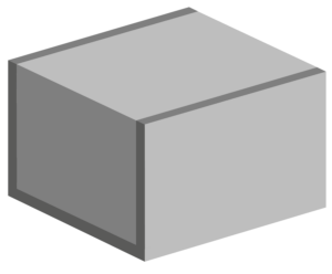
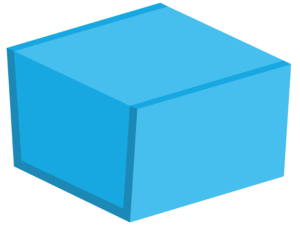
Avoid undercuts as much as possible. Simply designed molds with straight retraction do not produce parts with undercuts. This is because the part will then get stuck during ejection. Undercuts are only possible by changing the mold pitch or sliding cores in the mold. However, these drive up the mold costs considerably.
Changing the mold pitch or shifting the parting line is a particularly suitable means for undercuts on the outside of the casting.
At the parting line, both halves of the mold converge. Since the parting line leaves a visible seam (a flash) on the final product, they should be considered when designing your product. So it is best to place it where it is least visible. Although the casting flash can be removed by finishing after casting. However, this involves additional costs in the manufacturing process.

Screw Domes
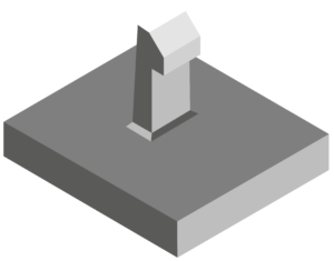
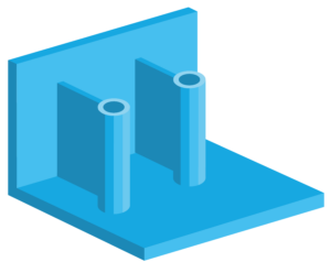
Screw domes are suitable for inserts, attachment pins or self-tapping screws. They are cylindrical spacers moulded into the plastic part.
Domes should not be free-standing but should always be attached to a side wall with a rib or to the base with a corner stiffener. To avoid visible sink marks on the outside, the thickness should not exceed 60% of the total thickness. For example, if the outer wall thickness is 3 mm, the ribs should not be thicker than 1.7 mm.
Sprue openings
Essential injection molding design tips for part design concern the location of sprue holes. Molten material enters the mould through sprue holes. Therefore, the location and type of opening must be well considered to avoid loss of quality.
Film sprues are most commonly used. Film sprues offer very good processing possibilities and can be enlarged if necessary. Since a film gate is tapered from the sprue, the smallest point is at the part surface. Therefore, the solidification point is between the part and the sprue, which means no heat is generated on the surface of the part. After the film gate has been manually removed, a 0.13 mm sprue remains.
In tunnel gating, a sprue is placed in the side of the part or in a bar sprue. The access to the part is created from the outside in the case of tunnel sprues, but the sprue residue usually remains small because it is halfway under the part surface. With bar sprues, however, you must be careful, as an unsightly shadow may remain on the opposite side of the part due to heat or part thickness. This type of gate should therefore be used with care on external parts.
Hot-tip gates are recommended because the sprues produce small amounts of waste. Hot-tip gates are best for parts that need to be filled evenly from the centre to the outer edges. This reduces mould shift, as film gates can create unbalanced pressure in a mould. Hot tip gates are often the best solution visually as they are about 1.3 mm in diameter and can be hidden in a logo or lettering.
The least visually appealing are direct taper gates. These have a large diameter that is difficult to remove and often require a fixture that is removed by milling. Direct taper gates are used on materials that have a high glass content or on parts where the centre requires finishing.
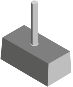
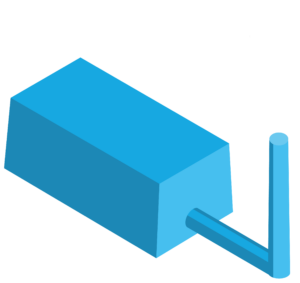 Use other sprue openings such as film sprues instead of direct taper gates.
